Imposing controlled axial deflection on a rotating shaft
Design notes on a swashplate mechanism I designed to solve a specific problem
Test requirement
The fixture must impose a controlled axial displacement once per shaft revolution and maintain that displacement during vibration.
The required axial displacement is ±0.004 inch during continuous rotation at 1800 and 3000 rpm. The part under test mounts on the end of the shaft. Axial motion must be reproduced at that mounting interface during vibration.
The motor provides rotation and the shaker provides vibration. A separate mechanism couples the rotation to one axial displacement cycle per revolution, with adjustable amplitude.
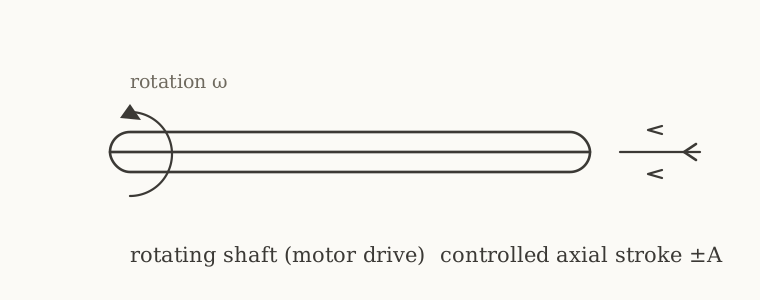
Swashplate mechanism
A swashplate uses an inclined disk to produce axial motion. When the disk is perpendicular to the shaft, rotation produces no axial displacement. Tilting the disk makes a follower on its face move axially once per revolution.
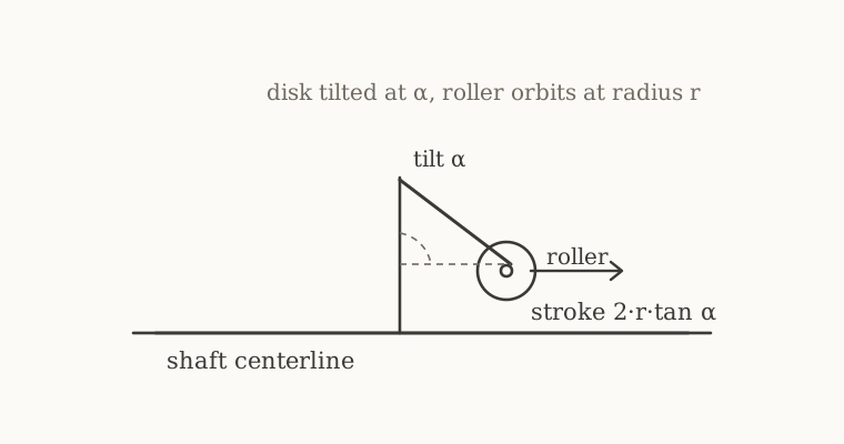
The peak axial displacement A is set by the contact radius and disk tilt:
A = r · tan α
where r is the radius at which the follower contacts the disk and α is the tilt angle. The axial displacement remains synchronized with shaft rotation, and its amplitude is adjusted through the disk tilt.
For ±0.004 in at a contact radius of about 0.6 in, the tilt is arctan(0.004 / 0.6) ≈ 0.38°, about 23 arcminutes.
Design 1: the spring-return follower
The first version used a die spring to hold a track roller against the tilted disk face.
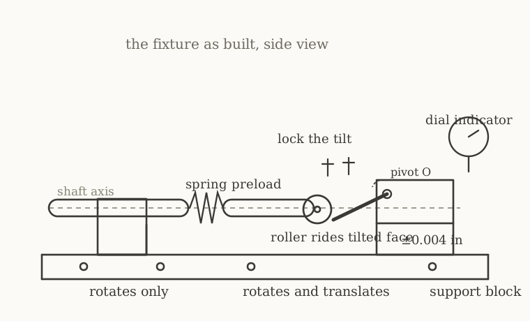
During the return stroke, the spring must accelerate the follower to maintain contact with the disk. Insufficient contact force can allow separation followed by impact, known as follower jump. I increased spring stiffness and preload to maintain contact.
Spring force and preload
The imposed axial stroke contributes an inertial load to the follower. The axial acceleration of the follower through a ±0.004 in stroke is Aω². At 3000 rpm that is about 1 g. At 1500 rpm it is a quarter of a g. Assuming a follower mass on the order of a kilogram, the stroke alone produces an inertial force of about 2 lbf.
The installed die spring applied approximately 100 lbf to the roller.
I selected a stiff die spring to prevent the roller from losing contact during vibration. At its installed compression, it applied approximately fifty times the estimated inertial force from the axial stroke alone.
The spring and follower also form an oscillator with natural frequency (1/2π)√(k/m). With the die springs I used, that frequency was between about 30 and 100 Hz. The rotation itself is 30 Hz at 1800 rpm and 50 Hz at 3000 rpm, and the vibration band runs from 10 to 2000 Hz. That range overlaps the rotational excitation frequencies and lies within the vibration band. Spring rate and installed compression therefore affect both the dynamic response and the contact preload.
Galling and bearing damage
The roller and disk face were both 440C stainless steel at the same hardness. The contact was dry and carried approximately 100 lbf of preload. Under that load the rolling surface galled, the roller failed, and the support bearing, a combined rotary-and-linear bushing running on a 17-4 shaft, galled and bent.
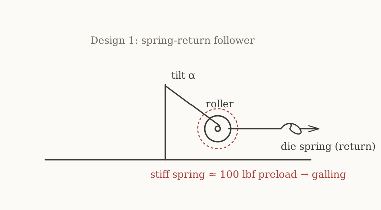
The redesign addresses contact preload and lubrication as well as the spring-return mechanism.
Design 2: the positive-return rolling yoke
The proposed redesign replaces the return spring with a two-sided drive. The tilted disk forms a rib with two parallel ground faces. A yoke, rigidly attached to the moving shaft, carries two rollers that straddle the rib, one on each face.
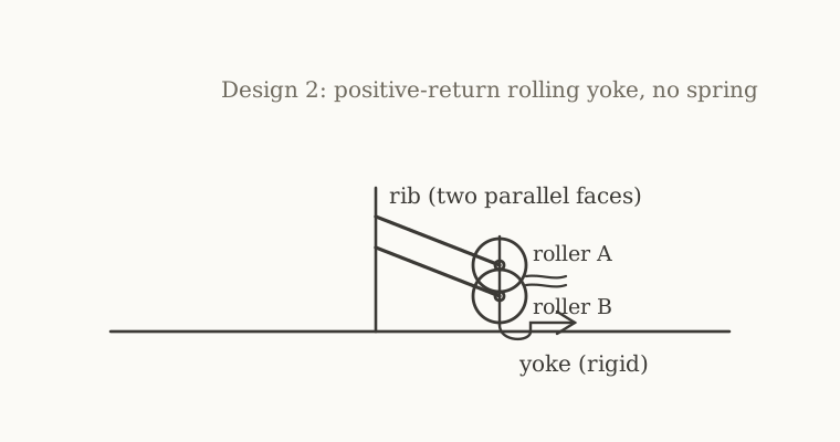
The near face drives the shaft outward and the far face drives it back. The two rollers constrain motion in both directions without a return spring. The proposed yoke preload is a few pounds, intended to keep both rollers seated and limit backlash.
This arrangement provides positive return, as in a conjugate or grooved cam. Running clearance in a grooved cam can produce lost motion at reversal. For a ±0.004 in stroke, the proposed clearance allowance is a few tenths of a thousandth of an inch. Preloading the yoke is intended to reduce that lost motion.
Tilt adjustment
At the assumed contact radius, ±0.004 in requires approximately 23 arcminutes of tilt. Holding the amplitude within ten percent requires setting the tilt within approximately 2 arcminutes.
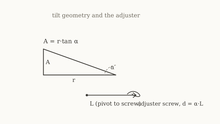
For the proposed adjuster geometry, a quarter-twenty screw changes the tilt by about 3.4 degrees per turn. A 100 threads-per-inch screw advances 0.01 inch per turn. A graduated collar is proposed to resolve adjustments below one arcminute. The screw pushes the rib's free end at a lever arm L from the pivot; the tilt is d/L, and the collar can be graduated directly in stroke units so the setting reads as axial displacement instead of an angle.
Materials and heat treatment
The rib faces act as bearing raceways. The proposed material is 440C stainless steel, through-hardened to 58 to 60 HRC with cryogenic treatment and double tempering, then ground and lapped to a surface finish of 4 to 8 microinch. The rollers are off-the-shelf 440C track rollers, already at that hardness. 440C is proposed for its corrosion resistance. Bearing life has not been established by the calculations presented here.
The moving shaft runs in a combined rotary-and-linear bearing, so its surface is a raceway too. The earlier 17-4 shaft at 44 HRC was too soft and gall-prone. The proposed replacement is carburized 8620 with a case hardness of 58 to 62 HRC over a tough core, ground after heat treatment to restore concentricity.
The proposed structural parts are 6061 aluminum. The pivot pin is hardened steel in a bronze bushing.
The proposed mechanism operates in an enclosed oil bath to lubricate the rolling contact, roller bearings, and shaft bushing. Any damping provided by the oil must be evaluated as part of the assembly response.
| Component | Material | Heat treatment and hardness | Finish or condition |
|---|---|---|---|
| Rib / disk raceways | 440C stainless steel | Through-hardened to 58 to 60 HRC; cryogenic treatment and double tempering | Ground and lapped to 4 to 8 microinch surface finish |
| Track rollers | 440C stainless steel | Supplied at 58 to 60 HRC | Off-the-shelf track rollers |
| Moving shaft | 8620 steel | Carburized case at 58 to 62 HRC over a tough core | Ground after heat treatment to restore concentricity |
| Structural parts | 6061 aluminum | Temper not specified in these notes | Finish not specified |
| Pivot pin | Hardened steel; grade not specified | Hardness and treatment not specified | Runs in a bronze bushing |
| Pivot bushing | Bronze; grade not specified | Treatment not specified | Finish not specified |
Verifying the stroke
The verification plan measures axial displacement during rotation and vibration. The proposed eddy-current probe would measure continuous axial position, with oil compatibility and bandwidth from DC to over 10 kHz to cover the 50 Hz stroke and vibration band. A button load cell at a known contact point would record contact force when the shaft reaches that position.
The first fixture verified the stroke with a dial indicator in dry runs. It was never measured during vibration. The proposed instrumentation is intended to measure displacement under vibration.
Design status
The design notes cover geometry, estimated forces, tilt adjustment, and material selection. The contact radius and the choice of fixed or field-adjustable tilt remain open. The proposed assembly still requires verification during rotation and vibration.